Page 3 of 9
Re: Three-way Axle Crimps
Posted: Wed Sep 05, 2018 7:32 pm
by Idris
Well, since we don't seem to know for certain what a peening tool actually looked like, anything's possible. However, these three-way axle crimps look so crisp and deliberate, I would be surprised yf they were anything other than an alternative axle finish. Furthermore, they only seem to occur on just two models, suggesting a limited, trial roll-out. (If they resulted from a peening head failure, we could expect to see them on as-good-as all models.)
Nevertheless, I agree with you that the occurrence of mixed axles on the same model very odd, counter-intuitive, and that an obvious explanation is lacking.
Re: Three-way Axle Crimps
Posted: Wed Sep 05, 2018 9:30 pm
by DrJeep
Idris wrote:If they resulted from a peening head failure, we could expect to see them on as-good-as all models
yes, good point. But from the few models here any trial appears to have been conducted over a relatively extended period - yellow and green 31b, 63a army ambulance with 10x24 and 11x45 wheels. That doesn't stop it being a trial, of course, or I suppose two separate trials. An intriguing mystery, anyway.
Re: Three-way Axle Crimps
Posted: Thu Sep 06, 2018 5:57 am
by Idris
All I can do is agree with you, Glenn: the timeline on all of this is extremely clouded.
Re: Three-way Axle Crimps
Posted: Thu Sep 06, 2018 8:10 pm
by Idris
I've been thinking a bit more about this, and I believe there is an interesting engineering consideration.
The three-way crimp results in a three-pointed Mercedes-type star being impressed into what would otherwise have been the peened end of the axle. This must result in the end of the axle spreading (a bit like a gun barrel in a cartoon when it blows up) in order for the wheel to remain on the axle. However, to be effective, the centre of the star must coincide with the centre of the axle, but the tool cannot be truly self-centring. If the tool fitted snugly over the end of the axle, the centres of both the tool and the axle would automatically align. However, when the 'Mercedes indent' was formed, the axle end would increase in diameter and the tool would then jam in place.
That leaves two possibilities: i) the jig idea already proposed (which neatly explains why only the rear axle on the 63a is found with this axle finish, but would be impracticale if a different jig were required for every axle on every model), or ii) the increase in axle diameter is sufficiently small that a tool with a large enough internal diameter to slide over the spread axle end would still align well enough on an unspread axle to yield an adequately centred star indent.
Could a member provide information on the diameters of the axle shaft and of the spread end please?
Re: Three-way Axle Crimps
Posted: Thu Sep 06, 2018 11:19 pm
by ClOwY
Hi Idris
(31b) axel shaft 158mm
the spread end is not 100 percent round but measures roughly 177mm.
hope this helps you
Gary
Re: Three-way Axle Crimps
Posted: Fri Sep 07, 2018 2:40 am
by yellowfoden
ClOwY wrote:Hi Idris
(31b) axel shaft 158mm
the spread end is not 100 percent round but measures roughly 177mm.
hope this helps you
Gary
My measurements with my 31b are similar to those from Gary and taken using NIB jaw electronic callipers.
Both axle diameter is 1.59mm
Three way axle end diameter is 1.85mm
Free end front axle riveted diameter is 1.95mm
On my spw there is virtually no slack between axle diameter and the wheel axle hole diameter.
So this means the burr to keep the wheel on the axle is only 0.26mm overall or a lip of 0.13mm all the way round the axle end.
Not much of an overhang, just slightly more than the thickness of copy paper.
Bert
Re: Three-way Axle Crimps
Posted: Fri Sep 07, 2018 9:22 am
by DrJeep
Idris wrote:If the tool fitted snugly over the end of the axle, the centres of both the tool and the axle would automatically align. However, when the 'Mercedes indent' was formed, the axle end would increase in diameter and the tool would then jam in place.
Wouldn't this problem also emerge with the normal peening machine, however it worked? The peened axle has to become bigger during the peening operation, but the peening needs to be centred, like this one
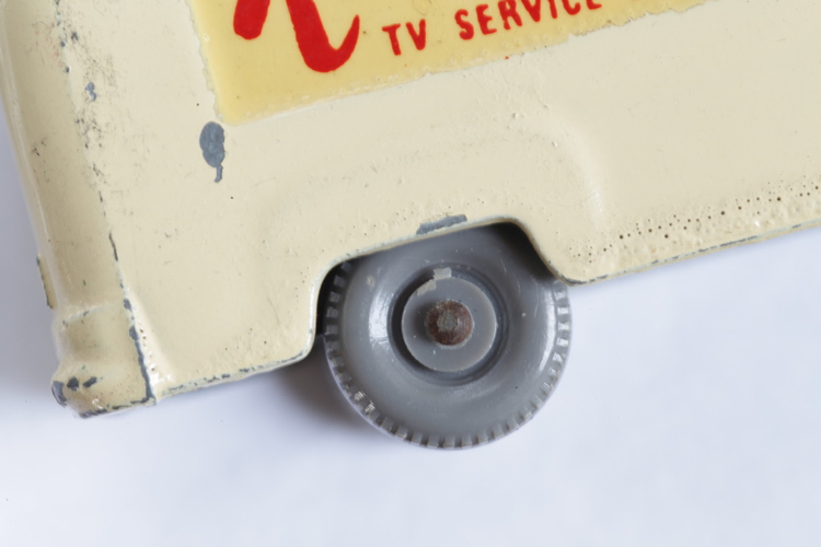
- IMG_5347.jpg (225.37 KiB) Viewed 9533 times
However it worked, Lesney knew how to centre an tool over an axle that expanded during the operation of that tool.
My peened yellow 31b has an axle of 1.53 mm and axle end of 1.75 mm, so pretty much the same as Bert's and Gary's.
Re: Three-way Axle Crimps
Posted: Fri Sep 07, 2018 8:05 pm
by Idris
DrJeep wrote:Wouldn't this problem also emerge with the normal peening machine, however it worked? The peened axle has to become bigger during the peening operation, but the peening needs to be centred, like this one.
I think of the peening tool as being something like an inverted hollow cone (which would be self-centring). The cone rotated, generating heat by friction when it was forced into contact with the axle end. The softened metal then flowed, resulting in a mushroomed axle end.
On the other hand, peened ends often display grooves, running from the centre to the outer edge. These are difficult to explain with the rotating cone theory unless the inside of the cone was ridged (and hardened) and the cone became stationary at the end of the downward (peening) stroke.
Re: Three-way Axle Crimps
Posted: Fri Sep 07, 2018 8:28 pm
by johnboy
Idris wrote:DrJeep wrote:Wouldn't this problem also emerge with the normal peening machine, however it worked? The peened axle has to become bigger during the peening operation, but the peening needs to be centred, like this one.
I think of the peening tool as being something like an inverted hollow cone (which would be self-centring). The cone rotated, generating heat by friction when it was forced into contact with the axle end. The softened metal then flowed, resulting in a mushroomed axle end.
On the other hand, peened ends often display grooves, running from the centre to the outer edge. These are difficult to explain with the rotating cone theory unless the inside of the cone was ridged (and hardened) and the cone became stationary at the end of the downward (peening) stroke.
That seems like a very good possibility, this has always had me wondering, the striations especially. Some axle ends have them although some don't. This could be because of the cone design or the amount of end-pressure. Using the theory above, the cones would be consumable items and require changing regularly due to wear or damage. Is it possible a rogue set of cones found their way into the supply somewhere and it is these which have caused the three way finish on the axle ends and this is just a tooling error?
Re: Three-way Axle Crimps
Posted: Fri Sep 07, 2018 8:50 pm
by Idris
Taking the most extreme values, the shaft diameter is 1.58 mm (probably a nominal 1/16” = 1.5875 mm) and the axle end is 1.85 mm diameter. That gives an expansion of 0.27 mm or about 17%.
Assume the three-way tool has an internal diameter of 3/32” = 2.38 mm (in order to have a safe clearance between the flared axle end and the tool). The centre of the star could then be a maximum of (2.38 – 1.58) / 2 = 0.4 mm off-centre. Given the axle radius of 1.58 / 2 = 0.79 mm, this is significant (at just over 50% of the total distance) and probably unworkable
Assume the three-way tool has an internal diameter of 5/64” = 1.98 mm. The centre of the star could then be a maximum of (1.98 – 1.58) / 2 = 0.2 mm off-centre. Given the axle radius of 1.58 / 2 = 0.79 mm, this is still significant (at just under 25% of the total distance), but probably not disastrous in terms of the finished article.
Are all the examples of these three-way axle ends currently available for inspection nicely centred (suggesting a very precise operation), or is there a degree of asymmetry in some of them (suggesting a more robust operation, better suited to mass production)?